Omron Pulse Servo (Cx-Programmer)
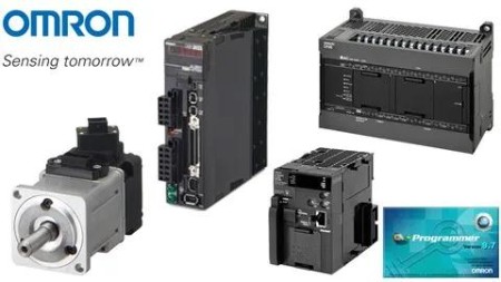
Omron Pulse Servo (Cx-Programmer)
Last updated 2/2022
MP4 | Video: h264, 1280x720 | Audio: AAC, 44.1 KHz
Language: English | Size: 4.94 GB | Duration: 7h 36m
Training to set up pulse input servers by Omron PLC using CX-Programmer
What you'll learn
Familiarity with servo drives and Learning pulse commands in PLC
The difference between absolute and relative movements
Home system in Servo based projects
Learn ready function blocks for servo systems in Omron PLC
What is Auto-TunConnect pulse outputs to the servo and step drive and What is Auto-Tune and how is it done?e and how is it done?
Requirements
Knowledge about CX-Programmer
Description
Lecture 1- Introduction of servo motor and servo drive hardware- Setting up a Servo systemIn this training lecture, you will get acquainted with servo motors and servo drives. What are the parts of a servo drive and servo motor and what models of PLCs do we need to control the servo drive through pulse?Lecture 2- Set up a Servo with pulse output- Show PLC wiring- Differences in types of pulse outputs- How to connect PLC and Servo- How to choose a servo- Introducing servo Inputs and outputsIn this lecture, you will get acquainted with some of the servo settings and we will explain servo drive cabling. You will also learn about different types of pulse outputs and then work with the inputs and outputs of a servo drive. Finally, we will teach you how to choose a serving system for your specific application.Lecture 3- Servo wiringIn this chapter, you will learn wiring between PLC and ServoLecture 4- Introducing the ACC instructionIn this chapter, you will get acquainted with the ACC instruction.In this chapter, you will get acquainted with the ACC instruction.ACC(888) outputs pulses to the specified output port at the specified frequency using the specified acceleration and deceleration rate.ACC(888) starts pulse output on the port specified in P using the mode specified in M using the target frequency and acceleration/deceleration rate specified in S. The frequency is increased every pulse control period (4 ms) at the acceleration rate specified in S until the target frequency specified in S+1 and S+2 is reached.The pulse output is started each time ACC(888) is executed. It is thus normally sufficient to use the differentiated version (@ACC(888)) of the instruction or an execution condition that is turned ON only for one scan.Lecture 5- Introducing the INI instructionIn this chapter, you will get acquainted with the INI instruction.INI(880) is used to start and stop comparison for a comparison table, to change the present value (PV) of a high-speed counter, to change the PV of an input interrupt in counter mode, to change the maximum value of the ring counter (CJ2M only), to change the PV of a pulse output (e.g., to 0 to establish the origin), to stop pulse output, or to change the settings for origin searches/returns (CJ2M only).Lecture 6- Introduction of pulse output flags- Start/Stop servo with slope by the ACC instructionWhen working with PLC pulse outputs, there are a number of flags that can be used in programming. In this training lecture, you will get acquainted with these flags and learn how to use them. Also in this lecture, a simple start and step servo program have been written with acceleration and deceleration using the ACC instruction.Lecture 7- Introducing the PRV instructionPRV (881) reads the High-speed counter PV and pulse output PV and interrupt input PV in counter mode.PRV (881) reads the data specified in C for the port specified in P. The possible combinations of data and ports are shown in the following table.(0000 to 0003 hex): Pulse output(0010 to 0013 hex): High-speed counter input(0100 to 0107 hex): Interrupt input in counter mode(1000 to 1003 hex): PWM (891) outputLecture 8- Introducing the SPED and PULS instruction- Introducing Absolute and Relative Movements- Solve a simple example of a reciprocating motionSPED (885) is used to set the output pulse frequency for a specific port and start pulse output without acceleration or deceleration.SPED (885) starts pulse output on the port specified in P using the method specified in M at the frequency specified in F. Pulse output will be started each time SPED (885) is executed. It is thus normally sufficient to use the differentiated version (@SPED (885)) of the instruction or an execution condition that is turned ON only for one scan.PULS (886) is used to set the pulse output amount (number of output pulses).PULS (886) sets the pulse type and a number of pulses specified in T and N for the port specified in P. Actual output of the pulses is started later in the program using SPED (885) or ACC (888) in independent mode.Lecture 9- Introducing the PLS2 instruction- How to draw a pulse output diagram in CX-ProgrammerPLS2(887) outputs a specified number of pulses to the specified port. Pulse output starts at a specified startup frequency, accelerates to the target frequency at a specified acceleration rate, decelerates at the specified deceleration rate, and stops at approximately the same frequency as the startup frequency.Lecture 10- Introducing CX-Drive software- Introduction of gearbox coefficient- How to convert a pulse to the desired unit and vice versa- How to tune a servoLecture 11- Introducing the Home conceptIn this lecture, we will look at the issue of home working with servo systems. What is Home and what are the different models of Home? We will also write a sample program for the homing servo.Lecture 12- Feed Examplethis lecture uses an input interrupt as a trigger to switch from speed control to position control and move the specified number of pulses.Lecture 13- Torque controlIn this lecture, you will learn about torque control mode in the servo. with this control mode, you can easily control the servo using the desired torque.Lecture 14- Speed controlIn this lecture, you will learn about servo speed control mode. In this control mode, you can control the servo speed by using analog inputs.Lecture 15- Introducing CP1L pulse outputIn this lecture, you will get acquainted with the pulse outputs of the CP1L model, and we will show that we do not need any special changes to control the servo with this PLC.Lecture 16Omron has prepared a series of function blocks to work with pulse outputs. Using these function blocks will make programming much easier. In this lecture, you will get acquainted with these function blocks.- Introducing the Omron function blocks- Move Absolute FB- Set Position FB- Read Actual Position FB- Move Relative FB- Move Velocity FB- Stop FB- Read Status FBLecture 17- Move Interrupt and solve a problemIn this lecture, you will get acquainted with the move interrupt function block and learn how to operate and use it.Lecture 18- Move Sequence FBIn this lecture, you will get acquainted with the move sequence function block and learn how to operate and use it.Lecture 19- How to get the gearbox coefficient- Convert speed and position and display in HMI- A practical example of Move Absolute with HMIIn this lecture, you will get acquainted with the gearbox coefficient. You will learn how to convert a pulse to a custom unit and display it on the HMI, and in the following, you will see a practical example of using the Move Absolute function.Lecture 20- A practical example of Move sequence with HMIIn this lecture, you will get acquainted with the move sequence function block and learn how to operate and use it. and also, we solve a practical example by using HMI.Lecture 21- Connecting Omron PLC to a Stepper Drive and running itIn this lecture, we will set up a step drive using pulse output. And we will show that in using the pulse outputs, there is no difference between setting up a servo drive or a step drive.Lecture 22- Introducing CP2E pulse outputIn this lecture, you will get acquainted with the pulse outputs of the CP2E model, and we will show that we do not need any special changes to control the servo with this PLC.Lecture 23- Introducing the ITPL instructionITPL (893) outputs a 2 to 4 axes linear interpolation to the specified port.ITPL (893) starts pulse output from the port specified in C1 (port0~3) using the method specified in C2 (axis2~4) at the start frequency (1 in the diagram) and acceleration/deceleration rate (2 in the diagram) in S.ITPL (893) supports at most 2 linear interpolation operations. The pulse output port method is determined by the settings of linear interpolative port specified in C1.The interpolated axes are determined by the settings specified in C2.
Overview
Section 1: Omron Pulse Servo (CX-Programmer)
Lecture 1 Introduction of servo motor and servo drive
Lecture 2 PLC wiring and pulse output types
Lecture 3 Servo wiring
Lecture 4 ACC instruction
Lecture 5 INI instruction
Lecture 6 Pulse output flags and sample program
Lecture 7 PRV instruction
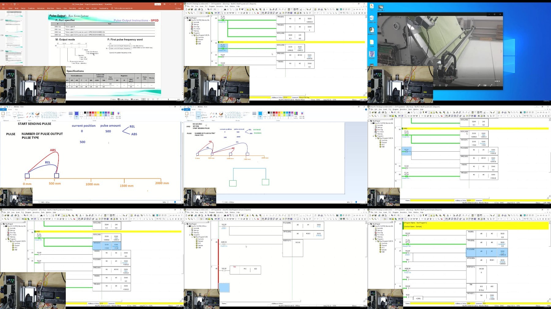
Lecture 8 SPED and PULS instruction
Lecture 9 PLS2 instruction
Lecture 10 Introducing CX-Drive, Gearbox coefficient
Lecture 11 Home concept
Lecture 12 Feed Example
Lecture 13 Torque control
Lecture 14 Speed control
Lecture 15 CP1L pulse output
Lecture 16 Omron Pulse Output Function Blocks
Lecture 17 Move Interrupt Function Block
Lecture 18 Move Sequence Function Block
Lecture 19 Gearbox Coefficient and Move Absolute Function Block
Lecture 20 Move sequence Function Block with an example
Lecture 21 Connecting PLC to Stepper Drive
Lecture 22 Introducing CP2E pulse output
Lecture 23 Introducing the ITPL instruction
For everyone that uses or wants to use Pulse/Analogue Servo Systems
https://ddownload.com/212515zjeuck/Udemy_Omron_Pulse_Servo_CX-Programmer.part1.rar
https://ddownload.com/yri34xfomc7u/Udemy_Omron_Pulse_Servo_CX-Programmer.part2.rar
https://ddownload.com/p183f73fm92m/Udemy_Omron_Pulse_Servo_CX-Programmer.part3.rar
https://rapidgator.net/file/4633551803cbdc5174314711fbeaf6f6/Udemy_Omron_Pulse_Servo_CX-Programmer.part1.rar
https://rapidgator.net/file/f4ea979b205ff89cd44c023a3d9ddb4f/Udemy_Omron_Pulse_Servo_CX-Programmer.part2.rar
https://rapidgator.net/file/bfa2caa63d669a9797f882fbc6334e26/Udemy_Omron_Pulse_Servo_CX-Programmer.part3.rar
https://filestore.me/gsjj2kemdvas/Udemy_Omron_Pulse_Servo_CX-Programmer.part1.rar
https://filestore.me/ixrst7mn312l/Udemy_Omron_Pulse_Servo_CX-Programmer.part2.rar
https://filestore.me/rrp7cyxn2ehl/Udemy_Omron_Pulse_Servo_CX-Programmer.part3.rar
What you'll learn
Familiarity with servo drives and Learning pulse commands in PLC
The difference between absolute and relative movements
Home system in Servo based projects
Learn ready function blocks for servo systems in Omron PLC
What is Auto-TunConnect pulse outputs to the servo and step drive and What is Auto-Tune and how is it done?e and how is it done?
Requirements
Knowledge about CX-Programmer
Description
Lecture 1- Introduction of servo motor and servo drive hardware- Setting up a Servo systemIn this training lecture, you will get acquainted with servo motors and servo drives. What are the parts of a servo drive and servo motor and what models of PLCs do we need to control the servo drive through pulse?Lecture 2- Set up a Servo with pulse output- Show PLC wiring- Differences in types of pulse outputs- How to connect PLC and Servo- How to choose a servo- Introducing servo Inputs and outputsIn this lecture, you will get acquainted with some of the servo settings and we will explain servo drive cabling. You will also learn about different types of pulse outputs and then work with the inputs and outputs of a servo drive. Finally, we will teach you how to choose a serving system for your specific application.Lecture 3- Servo wiringIn this chapter, you will learn wiring between PLC and ServoLecture 4- Introducing the ACC instructionIn this chapter, you will get acquainted with the ACC instruction.In this chapter, you will get acquainted with the ACC instruction.ACC(888) outputs pulses to the specified output port at the specified frequency using the specified acceleration and deceleration rate.ACC(888) starts pulse output on the port specified in P using the mode specified in M using the target frequency and acceleration/deceleration rate specified in S. The frequency is increased every pulse control period (4 ms) at the acceleration rate specified in S until the target frequency specified in S+1 and S+2 is reached.The pulse output is started each time ACC(888) is executed. It is thus normally sufficient to use the differentiated version (@ACC(888)) of the instruction or an execution condition that is turned ON only for one scan.Lecture 5- Introducing the INI instructionIn this chapter, you will get acquainted with the INI instruction.INI(880) is used to start and stop comparison for a comparison table, to change the present value (PV) of a high-speed counter, to change the PV of an input interrupt in counter mode, to change the maximum value of the ring counter (CJ2M only), to change the PV of a pulse output (e.g., to 0 to establish the origin), to stop pulse output, or to change the settings for origin searches/returns (CJ2M only).Lecture 6- Introduction of pulse output flags- Start/Stop servo with slope by the ACC instructionWhen working with PLC pulse outputs, there are a number of flags that can be used in programming. In this training lecture, you will get acquainted with these flags and learn how to use them. Also in this lecture, a simple start and step servo program have been written with acceleration and deceleration using the ACC instruction.Lecture 7- Introducing the PRV instructionPRV (881) reads the High-speed counter PV and pulse output PV and interrupt input PV in counter mode.PRV (881) reads the data specified in C for the port specified in P. The possible combinations of data and ports are shown in the following table.(0000 to 0003 hex): Pulse output(0010 to 0013 hex): High-speed counter input(0100 to 0107 hex): Interrupt input in counter mode(1000 to 1003 hex): PWM (891) outputLecture 8- Introducing the SPED and PULS instruction- Introducing Absolute and Relative Movements- Solve a simple example of a reciprocating motionSPED (885) is used to set the output pulse frequency for a specific port and start pulse output without acceleration or deceleration.SPED (885) starts pulse output on the port specified in P using the method specified in M at the frequency specified in F. Pulse output will be started each time SPED (885) is executed. It is thus normally sufficient to use the differentiated version (@SPED (885)) of the instruction or an execution condition that is turned ON only for one scan.PULS (886) is used to set the pulse output amount (number of output pulses).PULS (886) sets the pulse type and a number of pulses specified in T and N for the port specified in P. Actual output of the pulses is started later in the program using SPED (885) or ACC (888) in independent mode.Lecture 9- Introducing the PLS2 instruction- How to draw a pulse output diagram in CX-ProgrammerPLS2(887) outputs a specified number of pulses to the specified port. Pulse output starts at a specified startup frequency, accelerates to the target frequency at a specified acceleration rate, decelerates at the specified deceleration rate, and stops at approximately the same frequency as the startup frequency.Lecture 10- Introducing CX-Drive software- Introduction of gearbox coefficient- How to convert a pulse to the desired unit and vice versa- How to tune a servoLecture 11- Introducing the Home conceptIn this lecture, we will look at the issue of home working with servo systems. What is Home and what are the different models of Home? We will also write a sample program for the homing servo.Lecture 12- Feed Examplethis lecture uses an input interrupt as a trigger to switch from speed control to position control and move the specified number of pulses.Lecture 13- Torque controlIn this lecture, you will learn about torque control mode in the servo. with this control mode, you can easily control the servo using the desired torque.Lecture 14- Speed controlIn this lecture, you will learn about servo speed control mode. In this control mode, you can control the servo speed by using analog inputs.Lecture 15- Introducing CP1L pulse outputIn this lecture, you will get acquainted with the pulse outputs of the CP1L model, and we will show that we do not need any special changes to control the servo with this PLC.Lecture 16Omron has prepared a series of function blocks to work with pulse outputs. Using these function blocks will make programming much easier. In this lecture, you will get acquainted with these function blocks.- Introducing the Omron function blocks- Move Absolute FB- Set Position FB- Read Actual Position FB- Move Relative FB- Move Velocity FB- Stop FB- Read Status FBLecture 17- Move Interrupt and solve a problemIn this lecture, you will get acquainted with the move interrupt function block and learn how to operate and use it.Lecture 18- Move Sequence FBIn this lecture, you will get acquainted with the move sequence function block and learn how to operate and use it.Lecture 19- How to get the gearbox coefficient- Convert speed and position and display in HMI- A practical example of Move Absolute with HMIIn this lecture, you will get acquainted with the gearbox coefficient. You will learn how to convert a pulse to a custom unit and display it on the HMI, and in the following, you will see a practical example of using the Move Absolute function.Lecture 20- A practical example of Move sequence with HMIIn this lecture, you will get acquainted with the move sequence function block and learn how to operate and use it. and also, we solve a practical example by using HMI.Lecture 21- Connecting Omron PLC to a Stepper Drive and running itIn this lecture, we will set up a step drive using pulse output. And we will show that in using the pulse outputs, there is no difference between setting up a servo drive or a step drive.Lecture 22- Introducing CP2E pulse outputIn this lecture, you will get acquainted with the pulse outputs of the CP2E model, and we will show that we do not need any special changes to control the servo with this PLC.Lecture 23- Introducing the ITPL instructionITPL (893) outputs a 2 to 4 axes linear interpolation to the specified port.ITPL (893) starts pulse output from the port specified in C1 (port0~3) using the method specified in C2 (axis2~4) at the start frequency (1 in the diagram) and acceleration/deceleration rate (2 in the diagram) in S.ITPL (893) supports at most 2 linear interpolation operations. The pulse output port method is determined by the settings of linear interpolative port specified in C1.The interpolated axes are determined by the settings specified in C2.
Overview
Section 1: Omron Pulse Servo (CX-Programmer)
Lecture 1 Introduction of servo motor and servo drive
Lecture 2 PLC wiring and pulse output types
Lecture 3 Servo wiring
Lecture 4 ACC instruction
Lecture 5 INI instruction
Lecture 6 Pulse output flags and sample program
Lecture 7 PRV instruction
Lecture 8 SPED and PULS instruction
Lecture 9 PLS2 instruction
Lecture 10 Introducing CX-Drive, Gearbox coefficient
Lecture 11 Home concept
Lecture 12 Feed Example
Lecture 13 Torque control
Lecture 14 Speed control
Lecture 15 CP1L pulse output
Lecture 16 Omron Pulse Output Function Blocks
Lecture 17 Move Interrupt Function Block
Lecture 18 Move Sequence Function Block
Lecture 19 Gearbox Coefficient and Move Absolute Function Block
Lecture 20 Move sequence Function Block with an example
Lecture 21 Connecting PLC to Stepper Drive
Lecture 22 Introducing CP2E pulse output
Lecture 23 Introducing the ITPL instruction
For everyone that uses or wants to use Pulse/Analogue Servo Systems
https://ddownload.com/212515zjeuck/Udemy_Omron_Pulse_Servo_CX-Programmer.part1.rar
https://ddownload.com/yri34xfomc7u/Udemy_Omron_Pulse_Servo_CX-Programmer.part2.rar
https://ddownload.com/p183f73fm92m/Udemy_Omron_Pulse_Servo_CX-Programmer.part3.rar
https://rapidgator.net/file/4633551803cbdc5174314711fbeaf6f6/Udemy_Omron_Pulse_Servo_CX-Programmer.part1.rar
https://rapidgator.net/file/f4ea979b205ff89cd44c023a3d9ddb4f/Udemy_Omron_Pulse_Servo_CX-Programmer.part2.rar
https://rapidgator.net/file/bfa2caa63d669a9797f882fbc6334e26/Udemy_Omron_Pulse_Servo_CX-Programmer.part3.rar
https://filestore.me/gsjj2kemdvas/Udemy_Omron_Pulse_Servo_CX-Programmer.part1.rar
https://filestore.me/ixrst7mn312l/Udemy_Omron_Pulse_Servo_CX-Programmer.part2.rar
https://filestore.me/rrp7cyxn2ehl/Udemy_Omron_Pulse_Servo_CX-Programmer.part3.rar